This is the first article in a series that explores concepts of state in CircuitPython.
In this installment, we discuss the platform we're using (both CircuitPython and the Adafruit M0/M4 boards that support it), and build a simple circuit for demonstration purposes. We'll also talk a bit about abstraction.
This series is intended for people who are new to Python, programming, and/or microcontrollers, so there's an effort to explain things as thoroughly as possible. However, experience with basic Python would be helpful.
The Project, The Platform
All of the code and thought that in this article has its roots in a personal project. I wanted to make a low-impact tool to help me mouse more efficiently.
I found the answer in capacative touch. This is the same technology behind modern cellphones and touchscreens.
I was psyched when I found out that the Adafruit M0 series of microcontroler boards provided up to 7 touch capable pins and they can become USB interface devices that can emulate a mouse or keyboard (and more). With these boards, there's no need for an external board or IC for touch or USB control, all I need is an M0, some conductive objects, and some code and I can do some insanely cool stuff.
Warning
The M4 boards do not support capacitive touch.
These boards also provide power management either built-in or it can be easily added. It makes it easy to build a portable project that runs off of batteries, but still can be powered from the USB port (and in the case of a rechargable LiPoly battery pack, the USB port can be used to charge it as well).
What makes these boards a really killer platform for hobby projects is that the M0/M4 series also support CircuitPython, Adafruit's fork of MicroPython for these particular ARM controllers. It's Python, and one of the languages I'm most comfortable with.
Besides my personal preference, Python is a great language for learning, rapid prototyping, and general computing.
CircuitPython is being developed with the express goal of making MicroPython more accessible to new programmers. Because of this, it diverges a bit from MicroPython. MicroPython has already diverged a bit from standard Python as well.
The differences aren't significant enough to hinder people new to Python and/or microcontrollers, but if you already know MicroPython, or Python it might be a bit of an adjustment.
That aside, this is a really exciting platform. It stands to provide a gateway for non-programmers to get into computer science and electrical engineering. It's a great time to be alive!
It's not all 🌈's and 🦄's though. In spite of generally being a great platform, CircuitPython has some limitations, that everyone should be aware of. A much more powerful processor is required to run any flavor of MicroPython. Even with more power, the interpreted nature of Python makes code run, overall, slower than comparable compiled Arduino code.
Because a Python interpreter has to be constructed to execute Python code, the platform is also very RAM (random access memory) intensive. RAM is a precious resource on any microcontroller, and CircuitPython eats up a lot of working memory before our program even runs. People experienced with microcontrollers will be used to dealing with this, but because of the interpreter, you're at a disadvantage before your code is even loaded. Programs will start to run out of memory when they approach 150-200 lines of code. That includes external libraries. That's not a lot to work with.
Tip
We'll cover ways of reducing our memory footprint in this article. It's actually not as bad as it might seem.
Further, Python code, especially raw text, takes up a lot of space in another precious resource, flash memory. This is where our program code is stored. Again, this is nothing shocking if we've done any embedded development before, but using Python puts us at a bit of a disadvantage - our code can only be compiled down to an intermediary format, it can't be turned into compact machine code, so we have a lot less space to work with.
Beyond this, Adafruit has made it pretty clear that CircuitPython is geared toward beginners, and as such their priorities for adding features and the general design of the platform has that audience at the forefront. This can cause some frustration if you want to use a MicroPython or Arduino feature that hasn't been ported to CircuitPython, access an on-board peripheral or use an external IC/breakout board that Adafruit doesn't yet support.
Note
This sounds way more dire than it is, and is changing all the time. CircuitPython is still relatively new and is under constant development. 💖 Adafruit has done an amazing job of supporting the onboard peripherals and the chips and breakout boards they sell in CircuitPython.
I don't want to downplay what they've accomplished, but if you are coming from other MicroPython boards or the Arduino, or you aspire to build projects that use the full capacity of your microcontroller, you should be aware of what you're getting into.
With all that in mind, I'm happy to say Adafruit has done a great job overcoming the worst of these limitations with their M0 boards. Using the ARM based processors means much faster processor cycles - the M0 runs at 48Mhz, the M4 at 120Mhz (verses 8Mhz or 16Mhz for most common Arduino-compatible boards). There's a slowdown running Python on these boards, but for most applications it won't even be remotely noticeable.
These chips have a large amount of RAM to begin with, 32kb for the M0 and a whopping 192kb for the M4 (compared to 2Kb for most common/classic Arduino chips).
To address the issue of flash memory, Adafruit provides the express series of M0/M4 boards - they add in 2MB of extra flash memory that just works for storing Python code (you can use it as general storage as well).
In practice, with the right development boards, the advantages of CircuitPython far outweigh the downsides. In exchange for slightly more expensive components, limited low-level accessibility, and sometimes having to write less-than-elegant Python, we get an incredibly powerful platform for rapid prototyping. I've been using it for a few months now and have found it to be exceedingly capable.
What makes most of these concerns completely moot is that Adafruit's CircuitPython-compatible boards fully support the Arduino IDE. So if we can't work within the limitations of CircuitPython, we can always switch to the Arduino tooling, and unlock the full potential of the M0/M4 chips.
Audience
This guide is written for people who know basic Python, and have done rudimentary things with microcontrollers, like control LEDs and read from momentary switches.
It doesn't assume you are a Python expert, or have done anything too elaborate with microcontrollers - but it will expose you to some advanced concepts.
It's a good idea to work through Adafruit's "Welcome To CircuitPython" guide before trying to dig into the topics covered here, but it's not necessary.
Tip
It wouldn't hurt to also work through CircuitPython Essentials as well!
This series tries to dive really deep into details when exploring the concepts behind the code being developed. There are line-by-line explanations of each code example. So don't be afraid to give this guide a shot, even if you're really new to microcontrollers.
Please feel free to contact the author with questions, corrections, or suggestions on how to make this series more accessible!
Demo Project
To illustrate state in action, I've devised a simple, but not overly contrived demonstration project.
It consists of two buttons, a single one-color LED, and a single "addressable" RGB LED. I've chosen these particular components because they are easy to obtain and hook up. In fact, the single LED and RGB LED (a DotStar or NeoPixel depending on the board) come integrated on all CircuitPython-capable boards.
Tip
On the CircuitPlayground, even the buttons are already integrated!
The features of the demo project are as follows:
- Phase 1:
- One button will control the rate of blink of the red LED.
- The other button will turn the red LED on or off - it will not affect the blink rate.
- Phase 2:
- The functionality of Phase 1 will continue, except the RGB LED will blink as well. The "rate button" will change the blink rate of both LEDs.
- Pressing both buttons will change the color of the RGB LED.
- Phase 3:
- Functionality of Phase 2 will persist, except holding the other button will determine if the rate button is changing the blink rate of the RGB LED or the red LED. If it's held, the RGB LED rate is changed. If It's not held, the red LED rate is changed.
This is a fairly simple project but because of the complex button logic, it will really put our state and event code through its paces.
Materials
If you'd like to follow along, you will need the following items:
- A CircuitPython-capable development board (M0/M4 series, express recommended).
- Two momentary switches (buttons).
- A micro-USB cable.
- Connectors (jumper cables, alligator clips, solid-core wire; specifics will depend on which board you are using).
- A breadboard.
You can get all of these items from Adafruit, here's a list.
I've also sourced them and similar ones from Mouser, to give you some idea of possible substitutions: shared cart.
Amazon resellers will generally carry most of these things, even the Adafruit boards. It's a good idea to shop around, since there's a large gradient between cost, available options, shipping, and quality.
Note
I do not do affiliate links and do not endorse any particular storefront.
My point in providing saved carts and wishlists is to help you find what you need.
💖 That said, if given the opportunity, I will go on about Adafruit's quality and fast shipping, and this is based soley on my personal experiences with their online store and products. 🦄 💖
The Development Board
Any of the M0 or M4 based boards sold by Adafruit should be compatible with the code in this article.
I am fortunate to own, in part due to recent attendance at PyCon 2018, four examples of the M0 boards, and have tested the code on each:
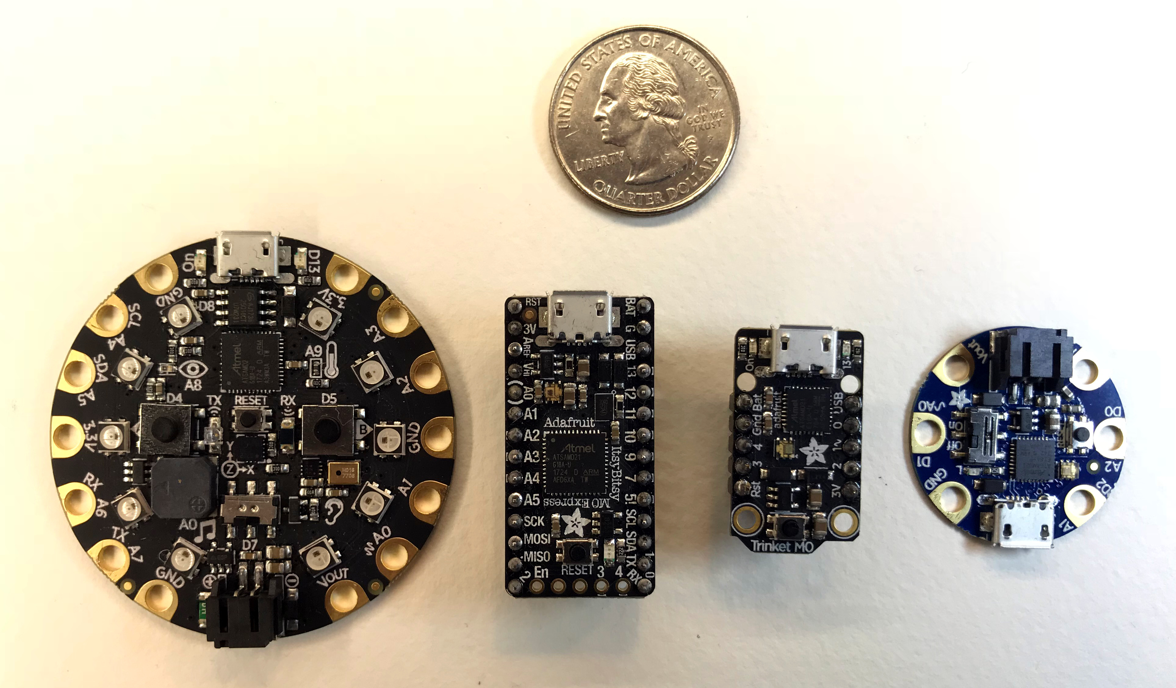
From left to right, we have the CircuitPlayground Express, the ItsyBitsy M0 Express, the Trinket M0, and the GEMMA M0. There's also a quarter for scale. On the whole, these things are tiny.
Note

The GEMMA M0 I have is a special edition that was included in the SWAG bag at PyCon 2018 in Cleveland Ohio. It's functionally identical to the GEMMA you get from the Adafruit shop but it's a different color and has a special Pycon 2018 marking on the back.
There was not a lot of fanfare about it, but I did find a video by Dan Bader talking about it, and a great blog post by Les Pounder putting it through its paces.
Which board should you use? It depends on your application, as each board has it's strengths.
The GEMMA, for example, is designed for wearable tech projects - it has a battery hookup and power regulator, as well as an on/off switch. The Trinket is absolutely lilliputian in its scale and a farily basic board. Both the GEMMA and Trinket have limited pins available. The ItsyBitsy and CircuitPlayground, being express boards, have extra flash memory. The CircuitPlayground has wearable features like the GEMMA, but it has a million nifty peripherals built in. It exposes a relatively small number of pins. In contrast, the ItsyBitsy is fairly barebones like the Trinket but has a lot of pins available.
The Feather boards (not pictured) have a ton of great built-in peripherals provide a standard platform for expansion boards called "wings". They are a great, super-compact alternative to the old-school Arduino and Arduino Shield platform. I have an ESP8266-based Feather and one based on the ATmega32u4 with bluetooth LE, and really like the platform.
Speaking of Arudino shields, Adafruit also makes an M0 board that's in the same form factor as the original Arduino, called the Metro M0 Express. If you've already invested in a lot of Arduino shields, this is the board for you.
In any case, I would highly recommend doing any initial development on the CircuitPlayground Express. It has a dizzying array of peripherals built in, plus battery and power regulation, along with a large number of easy-to-work-with pads - it's appropriate for wearable projects as well as more traditional applications. It's easy to migrate to a smaller/less featureful board when a project starts to really come together.
Tip
If your budget allows, and especially if you are just starting out, I'd suggest springing for the Circuit Playground Express Advanced Pack. I had a couple of M0 boards and a lot of miscellaneous breakout boards before I picked up this kit, and I wish I had started with it instead.
It gives you everything you need to explore the possibilities of the platform (save maybe some wire and a breadboard or two), without having to solder anything!
A few things to keep in mind with regard to the "lilypad" style boards (GEMMA, CircuitPlayground; so-called after one of the first "wearable" platforms, The Adruino LilyPad) verses the "standard" ones (Trinket, ItsyBitsy):
- Lilypad-style boards do not require any soldering or other assembly - you can just unpack them, plug in a USB cable, and start coding. You will typically use alligator clips, or conductive thread, to connect them to other components.
- Standard boards will require some soldering. You'll either have to solder wires directly to the pin pads on the perimeter of the board, or use the provided headers.
- You can, however, solder things to the lilypad-style pads for a sturdier connection.
Connectors
Here's an overview of the sorts of connectors used in the demo circuits below, and the sort of things to look for when buying kits or stocking out your workbench.
Tip
There are many ways to connect components to microcontrollers! This is just a sampling of some common ones, and the ones I used in the various demo circuits illustrated below.
Jumper Wires
The most common way to connect components in projects like ours is to use "jumper" wire - the term refers to the fact that the wire shorts (jumps) two points.
These are essential when working with breadboards.
You can make your own jumper wires using cut and stripped lengths of wire. The best to use for breadboard work is 22-gauge insulated wire, but anything that's conductive and between 18 and 24-guage should work.
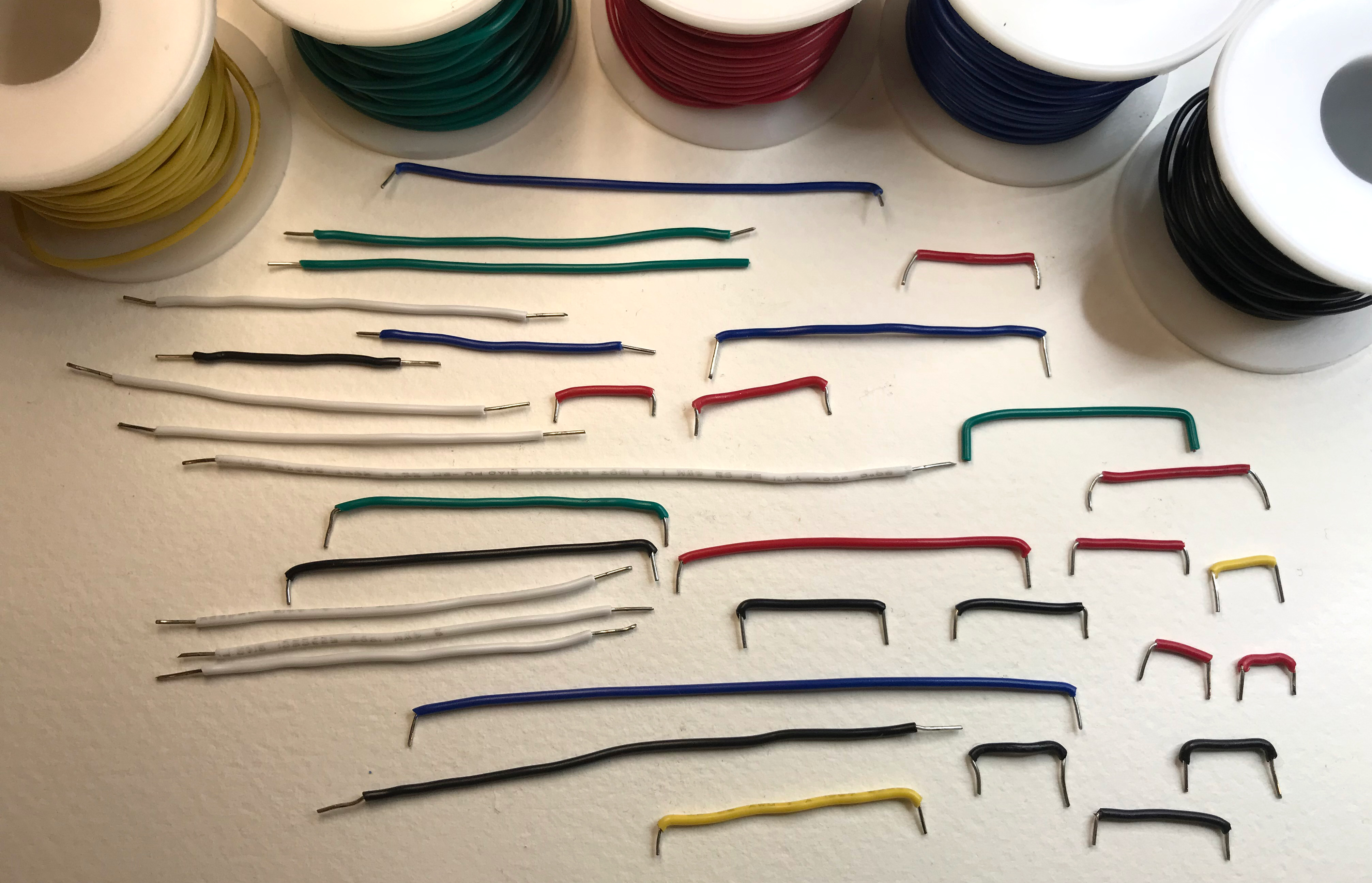
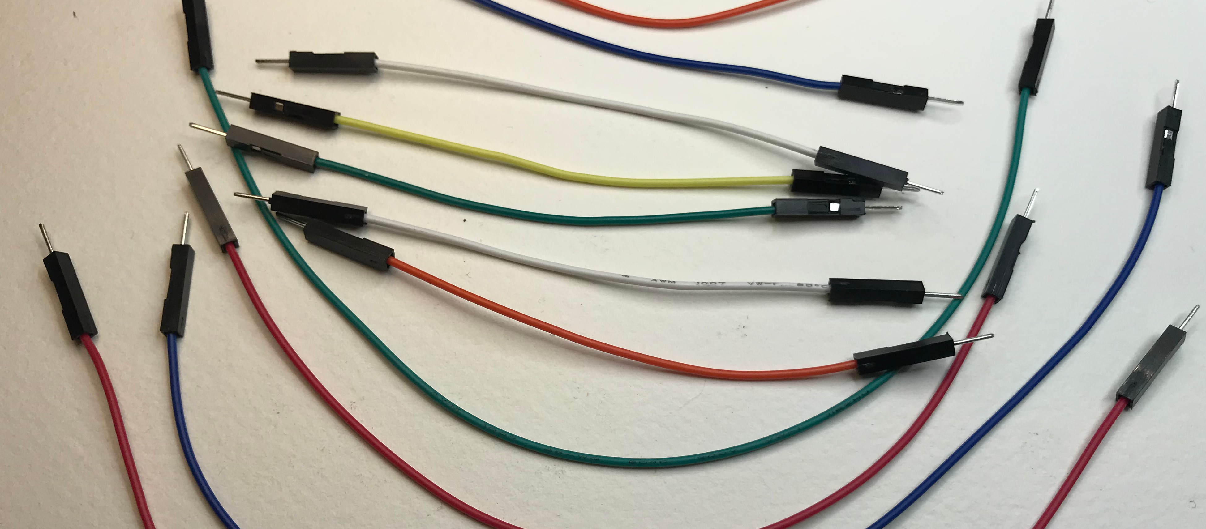
You can also buy "pre-made" jumpers. These are usually flexible stranded wire with "boots" or plastic shields covering the ends. They come in various lengths, colors, and combinations of "genders". "Female" refers to receptive connectors, and "male" refers to protruding ones.
For most projects (including this one), "male-to-male" wires are the go-to form.
Jumper wires will be required for any of the demo circuits for the ItsyBitsy or the Trinket. The GEMMA and CircuitPlayground will require other connectors, since they have those lilly-pad-style pads instead of standard pins.
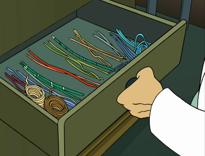
Eventually, you'll collect many of these lengths of wire, and will want to show them off, maybe by keeping them in a special drawer. 😀
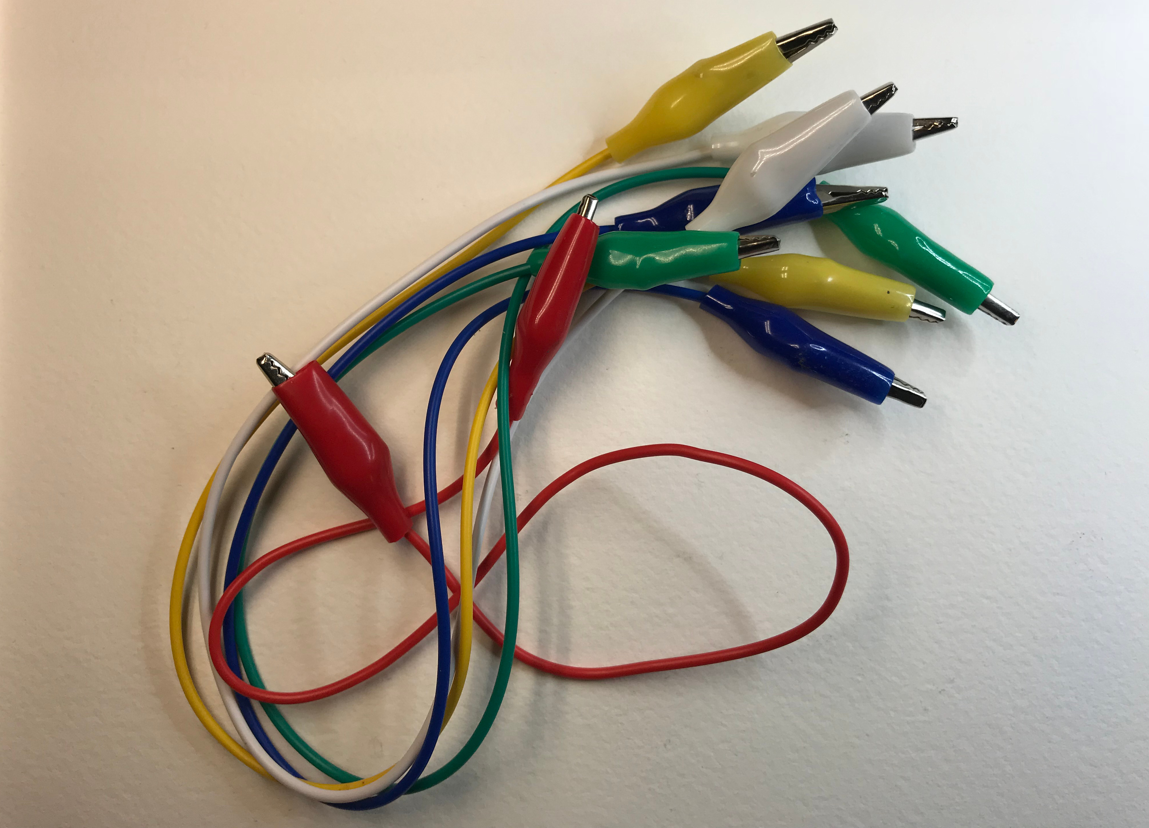
Alligator Clips
"Alligator" clips are called that because the spring-loaded connectors look sort of like an aligator's head. They come in many lengths and colors.
You can use alligator clips to connect anything conductive.
Alligator clips are essential for prototyping and general use of the "lilypad" style boards, like the GEMMA and CircuitPlayground.
In the demo circuits below, standard alligator clips aren't used, but they're a good addition to your toolbox, especially if you have one of the "lilypad" style boards.
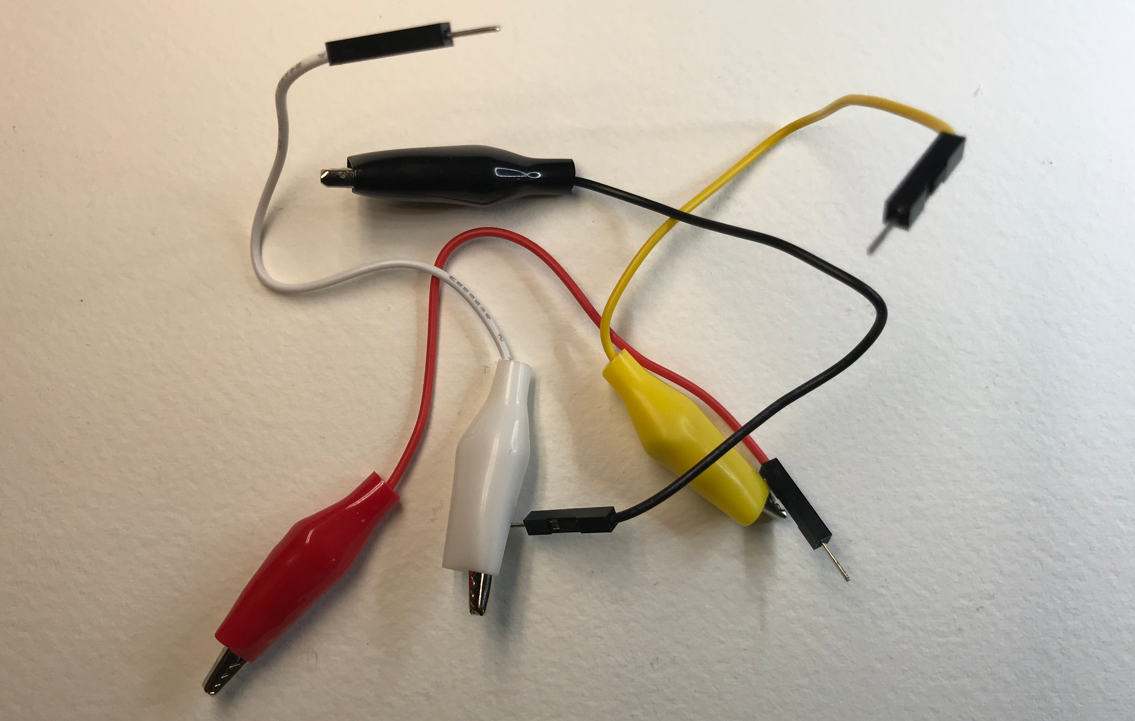
Alligator Clip To Jumper Wire
This is a variant connector that combines a alligator-style clip to a flexible jumper cable. They also come in different "genders".
We'll be using some of these in the "alligator-to-male" variety for the GEMMA version of the demo circuit.
The Demo Circuit
There are different ways you can set up buttons to work with the various M0 boards (save the CircuitPlayground, since it has them built-in), but for this article we'll use a breadboard and jumper wires.
The circuit ties one side of each button to ground, and then the other side to a pin on the board. This means that the buttons will read "LOW" when pressed. We'll use a "pull up" resistor to keep the high voltage from "floating". The resistor is built in to the microcontroller, so we can just turn them on in software.
I chose this approach for a few key reasons:
- It keeps the component count down - you don't need anything but the buttons and some wire. The other way of hooking up the buttons, where the button is tied to 3V, would require a resistor for each button. Most microcontrollers have pull up resistors built in these days, otherwise we'd also need an additional resistor for each pin as well.
- It's safer, since we're connecting the buttons, and ultimately the microcontroller pins, to ground instead of a live current. We can't do much, if any, damage if we misconfigure the pins in software, or the button is damaged (this is why we need the resistors if we were to wire the buttons up the other way).
- It's the most commonly used approach in the vast majority of tutorials and documentation these days, because of the previous two points. If you've used momentary switches with a microcontroller before, you're likely already familiar with this type of circuit.
The trade off is that the button logic seems inverted compared to what common sense would dictate: when we press the button, it reads "LOW", and when it's not pressed, it reads "HIGH".
The CircuitPlayground Express is wired in the reverse configuration, and requires a pull-down resistor turned on in software. The logic is also inverted to be "correct". This was done this way to make teaching easier with the board, but it adds an inconsistency in my little platoon of M0 development boards. This will be dealt with below, when we explore abstraction.
Tip
Lady Ada wrote a classic tutorial on the subject of wiring buttons to digital inputs. It explains everything, including the concept of "floating" really well. Highly recommended reading.
I've used three different kinds of breadboards I had on hand, and mixed up the kinds of connectors a bit to illustrate some different ways of wiring up the buttons.
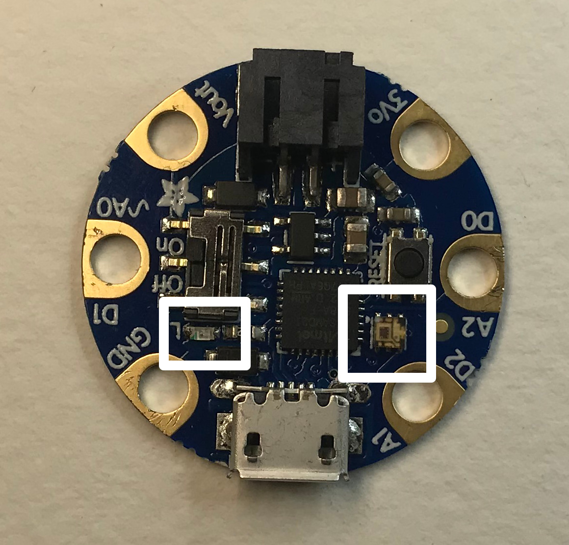
Gemma M0
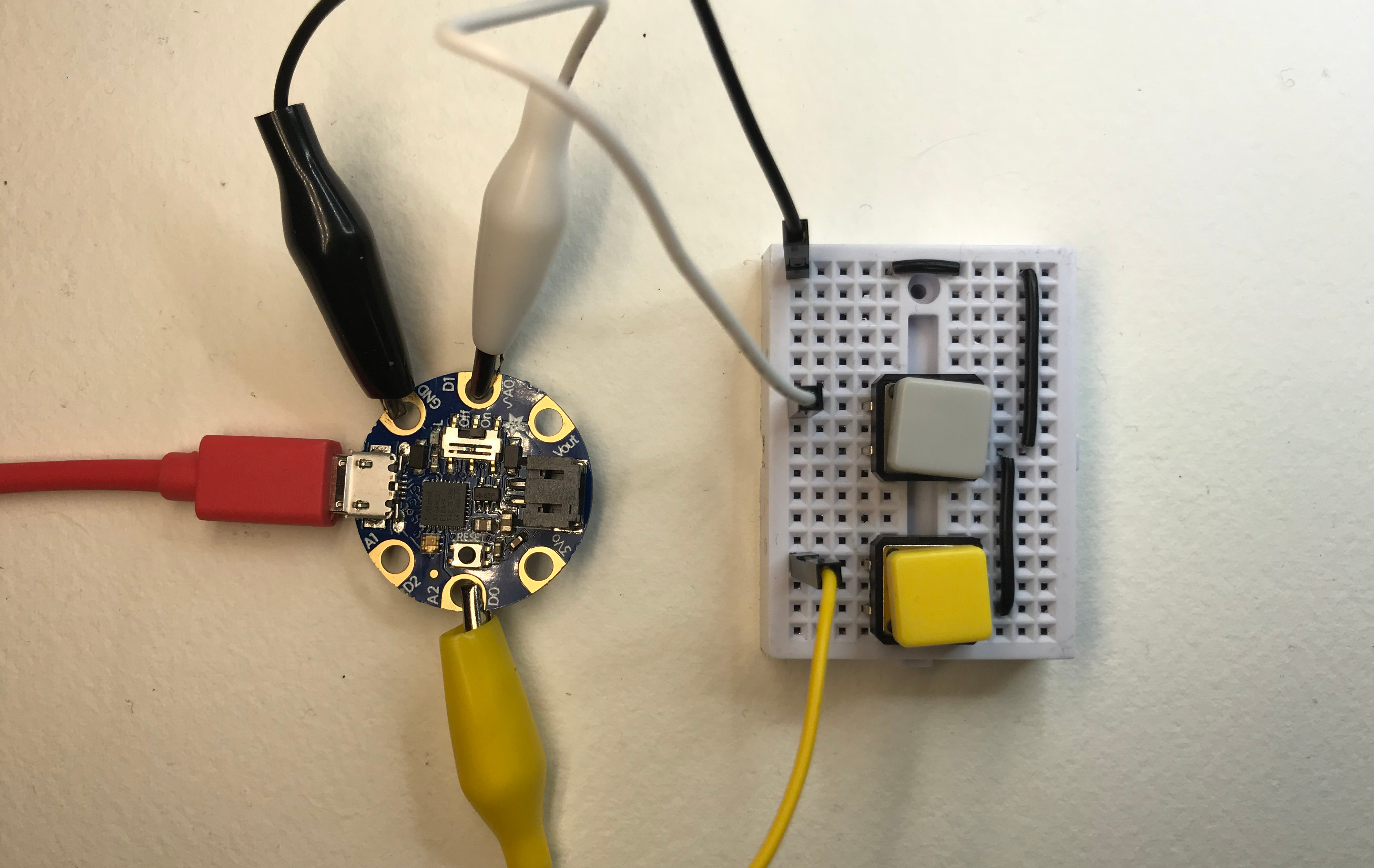
With the Gemma, I used a "mini" breadboard. These breadboards are split into two halves by the screw holes at the top and bottom, and the "trench" in the middle. The tie points are connected in groups of five, running left to right. I've installed the buttons such that they straddle the trench. This was necessary because of a little plastic bit that sticks out between the pins.
I wanted to make sure I had easy access to the buttons, so I put all of the jumper connections on the left side. On the right side, I made a little ground "bus" by tying together the rows where I needed to connect the buttons to ground with some solid-core wire. I tied the ground jumper/alligator clip to the "bus" using a little piece of wire over the screw hole.
I clipped the black alligator clip to ground, the white one (button "A") to "D1" (also marked "A0" if you use it as an analog pin), and the yellow clip/button to "D0" ("A2").
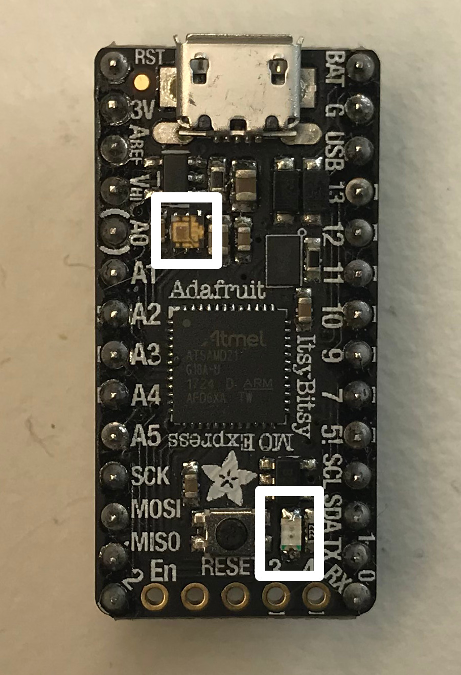
ItsyBitsy M0 Express
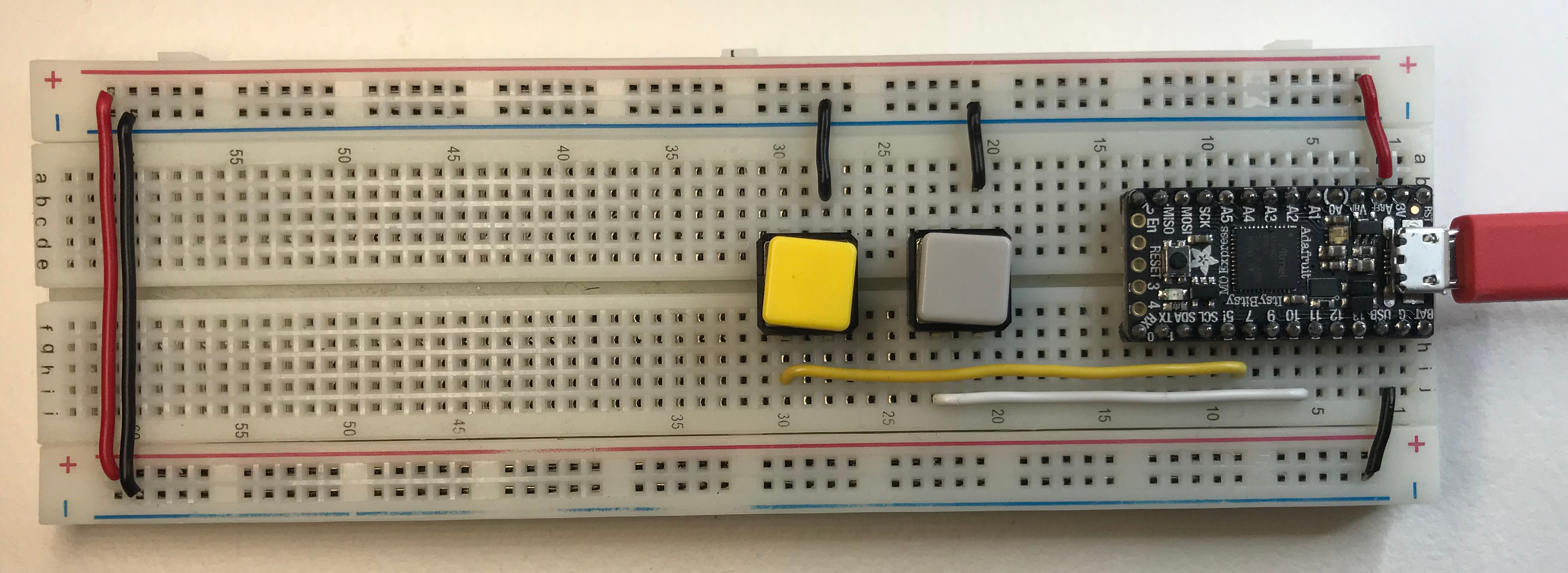
For the ItsyBitsy, I used a full-sized breadboard. On these breadboards, they have a similar split and trench down the middle. They also have a long bus on each side (top and bottom in this picture) marked negative and positive. Each group of tie points are connected. We've used them to run power from the ItsyBitsy to the rest of the board.
Tip
The buses can be removed and multiple breadboards can be connected to form larger areas to work with.
For ease of access, I've tied the left and right power rails together using some solid-core wire (far left). This isn't necessary for this project (we're only tying things to ground and pins on the ItsyBitsy), but it's a useful setup so I added it for demonstration purposes.
I've seated the ItsyBitsy, fitted with the supplied headers, into the top of the breadboard (row one, on the far right). I've tied it's 3V pin (positive 3.3 volts) to the top positive bus rail, and its G pin (negative, ground) to the negative rail on the bottom.
Because of the connections on the far left, all of the rails are live and connected like one big bus.
I've connected the buttons to ground on the top rail (rows 21, and 28).
I've connected button "A" (the grey button, white wire, row 23) to pin 11 on the ItsyBitsy (row 6 - "D11" in software).
I've connected button "B" (the yellow button, yellow wire, row 30) to pin 7 on the ItsyBitsy (row 9 - "D9" in software).
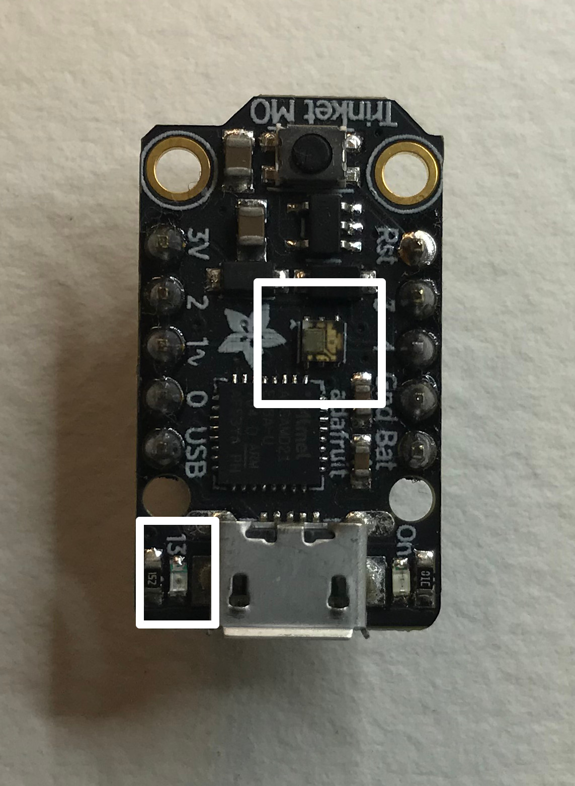
Trinket M0

For the Trinket, I used a standard "half-sized" breadboard. It's just like the "full sized" on I used for the ItsyBitsy, but it's... half the size 🤔.
For this circuit, I used pre-made jumper wires exclusively.
Tip
It's a little messier using all jumpers, but it's really easy to change things up. In fact, I originally had the buttons wired to pins on the other side of the Trinket, but it was hard to see what was going on in the pictures. It was trivial to rearrange things to make it easier to see what's what.
It's always a good idea to use jumper wires to start a project, and as things take shape, slowly replace them with solid-core wires. 🦄
I seated the Trinket with attached headers on row 1 (far right). I tied its ground ('Gnd' pin) to the left ground rail (-, in this picture it's on the top).
The buttons are tied to ground on the left side (rows 13 and 19).
The "A" button (grey, white jumper) is attached to pin "~1" (row 3, "D1" in software - this pin can also be an analog output, that's why it's marked with a tilde).
The "B" button (yellow, yellow jumper) is tied to pin 2 (row 4, "D2" in software).
CircuitPlaground Express: Problem Child
Doing things this way with the standard boards presents a problem with our rockstar board: the CircuitPlayground Express has its buttons wired in the other manner. They require a pull-down resistor turned on in software, and will read "HIGH" when pressed.
Further, the pin assignments are different for every single board, and the boards differ in what kind of RGB LED they have onboard. In the next section, we'll address these minor differences with some clever Python code and the power of abstraction.
Abstractions: Keeping The Code Simple
Because there are minor differences between the different boards, we're going to abstact them away using a python module. We'll call it setup.py.
In programming, abstraction is providing an indirect way to work with something. That something might be code, concepts, a service like a database, or something physical like different development boards, as we're abstracting here.
Abstraction helps by providing a single, simplified interface to do things that may have a lot of complexity.
For example, instead of building an abstraction module like we're doing below, we could have a bunch of if statements that, given we have a way to figure out what board we're running our code on, set up the right pins or pixels for us.
Something like this:
1 2 3 4 5 6 7 8 9 10 11 12 13 14 15 16 17 18 | # psuedo code!
if itsy-bitsy:
set up dotstar
use pins D7 and D11
set up led on pin D13
elif circuit-playground:
set up neopixel
use pins D4 and D5
set up led on pin D13
elif trinket:
set up dotstar
use pins D1 and D2
set up led on pin D13
elif gemma:
set up dotstar
use pins D0 and D1
set up led on pin D13
|
The problem with this approach is that, besides being messy, it's adding a lot of extra places where our code could break. And every new board you want to use adds more complexity.
But more importantly, you have to know every detail of every board you might use. Maybe someone wants to use our code and their LED is on pin 3. Maybe they are using touch pads instead of buttons. Maybe there's some new-fangled RGB LED product (we'll call them SunSpots™ 😉) that someone wants to use.
If we have this chain of if's, its up to us to add in support for these different ways of doing what we want to do.
In an abstraction, we decide on a standard way of accessing the code, or interface. That means we decide that variables and functions will be named a certain way. Functions will take certain parameters and return specific kinds of values.
Tip
Like many terms in technology, interface has multiple meanings in different contexts.
We're using the term in the sense of an application programming interface, usually abbreviated as API.
Be careful when searching 😀.
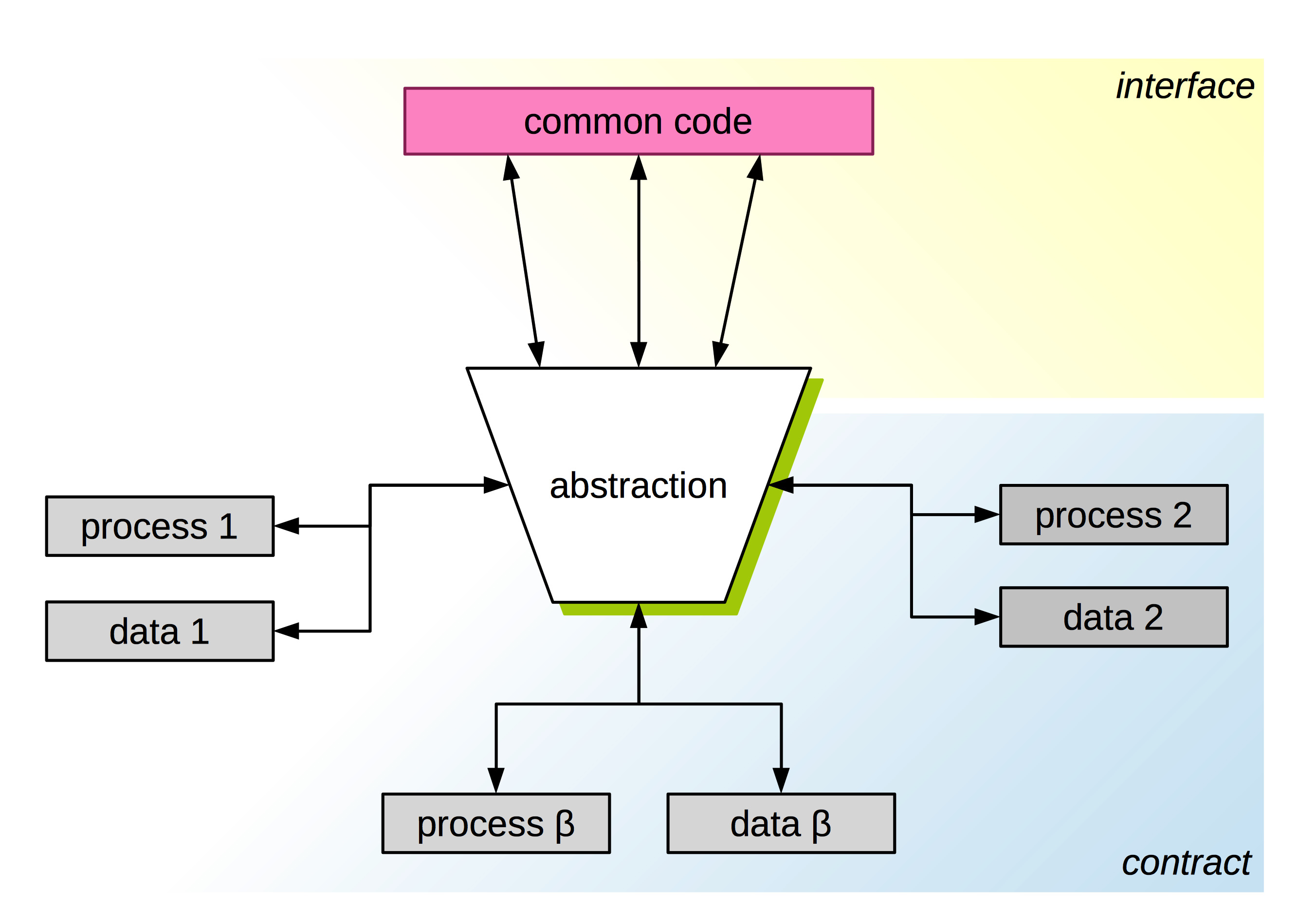
Another term for this, that you'll hear used sometimes in computer science, is contract. I think that describes what the abstraction does a bit more concisely - you are saying to someone who wants to use your code "I promise that you can rely on my code working this way", and the user is saying "I agree to do things your way".
As long as the code for each board follows the contract, and anyone using the board-specific code does so through the interface, everything works in an interchangeable way.
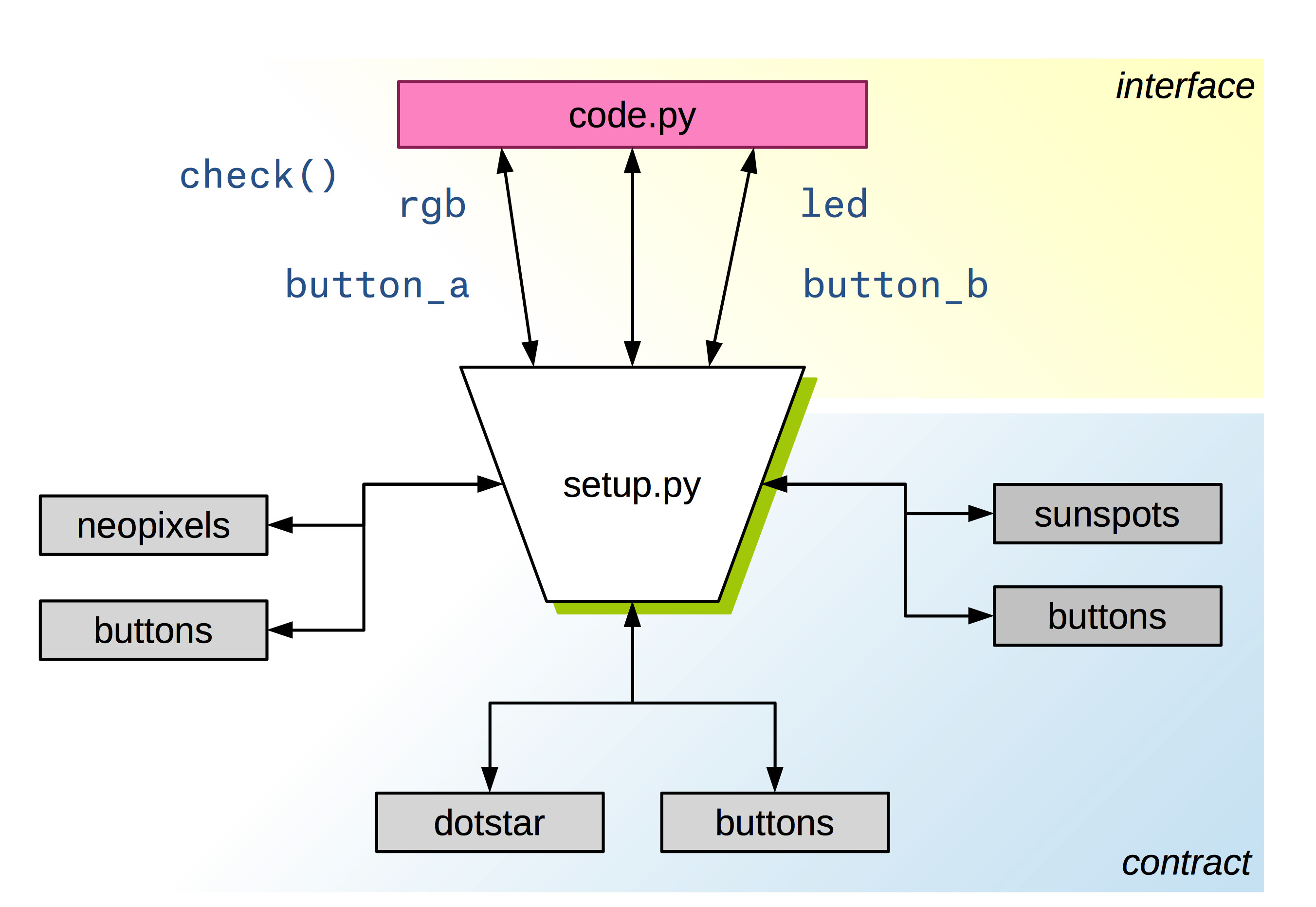
I like to think about the interface in terms of the actual variables and functions you use, and the contract as the understanding of what inputs and outputs the interface uses, as well as the things the interface does when you call the functions or access the variables:
For this simple abstraction, I've decided to make five Python objects that define our interface:
- A pixel object (rgb)
- The built-in RED LED, represented by a DigitalInOut object (led)
- 2 buttons, represented by DigitalInOut objects (a_button, b_button)
- A function that returns the value of a button (check()).
These are the bits of code used by the demo project that will be different from board to board.
We'll put them into a Python module called setup. Python modules are usually just Python files, so we'll store our abstraction in a file called setup.py.
To use our abstraction, we just need to import setup and then we can access, for example, setup.rgb to mess with the RGB pixel. That actual variable might be a NeoPixel. It might be a DotStar. It might be something we've never heard of (like a SunSpot™). It could be wired to any pin, configured any way. It doesn't matter. As long as that rgb object works the same way (has the same interface) as a DotStar or NeoPixel, it complies with the contract and everything works:
🦄 There's even a nested abstraction here. Adafruit has already abstracted the pixel code away for us, by giving the DotStar and NeoPixel classes the same interface. So we can interact with a string of NeoPixels in the same way we can interact with a string of DotStars.
Tip
If someone wanted to use a different kind of RGB LED (SunSpots™), as long they adhere to the interface of the abstraction Adafruit has provided, our code will still work. In fact, the SunSpots™ library would work anywhere DotStar or NeoPixel are used.
Now anyone who wants to follow this article, but maybe has a pyboard or an ESP8266-based board can follow along without having to constantly adapt the code to their situation. All they have to do is write a setup.py module and make sure it has the expected objects.
So here's the code for each of the boards I have.
Note
If you are using a board that has a built-in NeoPixel, but isn't a CircuitPlayground, use the DotStar code, but replace the DotStar lines (lines 3, 8 and 9) with the NeoPixel code from the CircuitPlayground example.
For the CircuitPlayground
1 2 3 4 5 6 7 8 9 10 11 12 13 14 15 16 17 18 19 20 21 22 23 24 | # save as setup.py
import board
import neopixel
from digitalio import DigitalInOut, Direction, Pull
led = DigitalInOut(board.D13)
led.direction = Direction.OUTPUT
rgb = neopixel.NeoPixel(board.NEOPIXEL, 1)
rgb.brightness = 0.3
a_button = DigitalInOut(board.D4)
a_button.direction = Direction.INPUT
a_button.pull = Pull.DOWN
b_button = DigitalInOut(board.D5)
b_button.direction = Direction.INPUT
b_button.pull = Pull.DOWN
def check(token):
if token == "A":
return a_button.value
if token == "B":
return b_button.value
|
Explanation
This file will need to be saved on your CIRCUITPY drive as setup.py.
Lines 2-4 import external libraries needed for this module to function.
The board library contains variables that are related to your specific development board. It contains all of the pin assignments, including some handy aliases for the built-in components (like the board.NEOPIXEL variable used on line 9).
The neopixel library gives us a way to control the 10 RGB LEDs that surround the CircuitPlayground. Depending on how your CircuitPython was installed, you may have to install this library yourself. This process is covered in detail on the CircuitPython Libraries section of the "Welcome To CircuitPython" guide.
The basics of the neopixel library, specifically for this board, are disucessed in the documentation.
NeoPixels are a hugely cool peripheral, and you are not limited to just using the ones on your CircuitPlayground Express. Check out the NeoPixel Überguide for comprehensive information about them.
On line 4, we import a few things from the digitalio library. This library contains classes, variables and functions useful for reading and writing to digital pins (buttons, LEDs, etc). We're only importing the objects that we need to set up the buttons and built-in LED, DigitalInOut, Direction, and Pull. Their purpose will be explained shortly.
Lines 6 and 7 set up the built-in red LED. It's attached to digital pin 13, so we pass board.D13 to the DigitalInOut constructor. On Line 7, we set the direction of the pin to be an output - this means the pin is only going to be used for sending information, on in this case, sending power to the pin to turn on the LED.
led is now a DigitalInOut object we can write to by setting its value attribute to a boolean value (True or False).
Lines 9 and 10 configure the NeoPixel. We call the NeoPixel object simply rgb to keep it as generic as possible. When we call the NeoPixel constructor, neopixel.NeoPixel, we pass the pin where our pixels are installed (board.NEOPIXEL), and the number of pixels we want to illuminate. We have 10 pixels available, but since we are mimicking a board with just one built-in, we pass 1 to the constructor.
On Line 10 we set the brightness of the pixel to 0.3. The brightness is a float between 0 and 1.0. These pixels are incredibly bright, feel free to lower this to 0.1 if 0.3 is too intense, or increase it if you want to really light up your life. 😀
Lines 12-14 and lines 16-18 set up our buttons. In the case of the CircuitPlayground, these are the built-in buttons, and need a pull-down resistor turned on to function. The pins are supplied via the board module. The direction is set just like the led on line 6, but in this case the direction is set to Direction.INPUT, because these are pins to be read from, instead of written to. Finally on lines 14 and 18, we enable the pull-down resistor using the pull property and the Pull object from the digitalio module.
Finally, on lines 20-24, we define a function called check(). The purpose of this function is to abstract away the differences between how these various boards are wired up. In the case of the CircuitPlayground, the onboard buttons are wired in the "sane" manner such that pressing the button causes the pin to read True, and not pressing the button, causes the pin to read False. This is the opposite of how the other boards are configured.
This function will always return True if the button is pressed, and False if it's not, regardless of how the buttons are set up.
check() takes a single parameter, token, which is used to indicate which button you want to check the value of. It's a simple string - when it's set to "A", check() returns the value of the "A" button (button_a), and when it's set to "B", check() returns the value of the "B" button (button_b).
For the other boards with DotStars
Note
Be sure to change the pin numbers to reflect how you wired up your buttons.
1 2 3 4 5 6 7 8 9 10 11 12 13 14 15 16 17 18 19 20 21 22 23 24 | # save as setup.py
import board
import adafruit_dotstar
from digitalio import DigitalInOut, Direction, Pull
led = DigitalInOut(board.D13)
led.direction = Direction.OUTPUT
rgb = adafruit_dotstar.DotStar(board.APA102_SCK, board.APA102_MOSI, 1)
rgb.brightness = 0.3
a_button = DigitalInOut(board.D4)
a_button.direction = Direction.INPUT
a_button.pull = Pull.UP
b_button = DigitalInOut(board.D3)
b_button.direction = Direction.INPUT
b_button.pull = Pull.UP
def check(token):
if token == "A":
return not a_button.value
if token == "B":
return not b_button.value
|
Explanation
This file will need to be saved on your CIRCUITPY drive as setup.py.
Lines 2-4 import external libraries needed for this module to function.
The board library contains variables that are related to your specific development board. It contains all of the pin assignments, including some handy aliases for the built-in components (like the board.APA102_SCK variable used on line 9).
The adafruit_dotstar module provides a way to control DotStars. DotStars are like NeoPixels, but use a different protocol. The differences are explained on the DotStar LED docuemntation page.
You will have to install the adafruit_dotstar library. This process is covered in detail on the CircuitPython Libraries section of the "Welcome To CircuitPython" guide.
The details of working with the DotStar library in CircuitPython is covered in the CircuitPython DotStar section of the CircuitPython Essentials document.
On line 4, we import a few things from the digitalio library. This library contains classes, variables and functions useful for reading and writing to digital pins (buttons, LEDs, etc). We're only importing the objects that we need to set up the buttons and built-in LED, DigitalInOut, Direction, and Pull. Their purpose will be explained shortly.
Lines 6 and 7 set up the built-in red LED. It's attached to digital pin 13, so we pass board.D13 to the DigitalInOut constructor. On Line 7, we set the direction of the pin to be an output - this means the pin is only going to be used for sending information, on in this case, sending power to the pin to turn on the LED.
led is now a DigitalInOut object we can write to by setting its value attribute to a boolean value (True or False).
Lines 9 and 10 configure the DotStar. We call the DotStar object simply rgb to keep it as generic as possible. DotStars are connected via SPI, so they require two pins to be specified in the constructor. We use the board library to provide the two built-in pins that are pre-wired to all built-in DotStars, board.APA102_SCK and board.APA102_MOSI. Finally we pass 1 to the constructor, to let the library know we are only controlling the single DotStar.
On Line 10 we set the brightness of the pixel to 0.3. The brightness is a float between 0 and 1.0. These pixels are incredibly bright, feel free to lower this to 0.1 if 0.3 is too intense, or increase it if you want to really light up your life. 😀
Lines 12-14 and lines 16-18 set up our buttons. The pins are supplied via the board module. The direction is set just like the led on line 6, but in this case the direction is set to Direction.INPUT, because these are pins to be read from, instead of written to. On these boards, we've wired all of the buttons so they connect to ground when pressed, so we have to use a pull up resistor so they function properly (lines 14 and 18) . This also means that our logic will be inverted relative to other wirirings (and common sense) - when the button is pressed, the pin will read False, and when it's not pressed, it will read True.
Finally, on lines 20-24, we define a function called check(). The purpose of this function is to abstract away the differences between how these various boards are wired up. On lines 22 and 24, we use the not operator to negate whatever we got from the button pin. This normalizes the output between these boards, and boards like the CircuitPlayground that are wired in the opposite manner.
This function will always return True if the button is pressed, and False if it's not, regardless of how the buttons are set up.
check() takes a single parameter, token, which is used to indicate which button you want to check the value of. It's a simple string - when it's set to "A", check() returns the value of the "A" button (button_a), and when it's set to "B", check() returns the value of the "B" button (button_b).
How It Works
To use this in our other code (code.py), we just need to use Python's import statement:
1 | from setup import led, rgb, check
|
Now, in our code, we use the led variable to turn the red LED on/off, and use rgb to control the NeoPixel/DotStar. We will use the check() function to see if a button is being pressed, like this:
1 2 3 4 5 6 7 8 9 | if check("A"):
print("Button A has been pressed")
else:
print("Button A has not been pressed")
if check("B"):
print("Button B has been pressed")
else:
print("Button B has not been pressed")
|
Testing
Before digging into state and other fun stuff, its a good idea to run some super simple code to ensure that everything is wired up properly. I've written some minimalistic code you can use to verify everything is set up.
What this code does is turn the on the onboard LED when button "A" is pressed, and the RGB LED (either a dotstar for the ItsyBitsy, Trinket, or GEMMA boards, or a NeoPixel in the case of the CircuitPlayground) when button "B" is pressed.
Tip
For details about controlling the onboard RGB LEDs, see Adafruit's excellent documentation on the subject.
Before running this code, make sure you've copied the proper RGB LED library over to your board, in the lib folder.
Tip
If you aren't familiar with this process, check out the CircuitPython Libraries section of the "Welcome To CircuitPython" guide.
Also make sure you have created a setup.py module, as explained in the last section.
1 2 3 4 5 6 7 8 9 10 11 12 | import time
from setup import led, rgb, check
while True:
led.value = check("A")
if check("B"):
rgb[0] = (255, 255, 255)
else:
rgb[0] = (0, 0, 0)
time.sleep(0.2)
|
Explanation
- Lines 1 and 2 import the necessary external objects and modules we need.
- The time module provides functions related to the passage of time, usually in terms of seconds.
- Line 4 starts off the standard "main loop" where our code runs.
- On Line 5, we set the value of the led object, or the red LED wired to pin 13, to whatever the value of the "A" button happens to be at that moment. If the value is True (the button is pressed), the LED will turn on. If it's False (the button is not pressed), the LED will turn off.
Lines 7-10 have a similar function to line 5, except that the RGB LEDs are not simple on/off devices. They must have a color of some kind written to them, usually a tuple of three integers, each ranging from 0 to 255. Each integer in the tuple corresponds to a red, green, and blue LED element in the pixel (respectively), and sets its intensity level.
The NeoPixel and DotStar libraries provide an interface such that you can treat the pixel object like a standard Python list. This is how we are able to write a color to the first pixel using list indexing on lines 8 and 10.
In the case of line 10, we're writing "black" to the pixel by setting the red, green and blue values to 0 (by passing the tuple (0, 0, 0)). This has the effect of turning it off, in the same way that setting the led.value property to False turns the red LED on pin 13 off.
Finally on line 12, we call time.sleep() to pause the program for 0.2 seconds. This provides simple button debouncing (much more about button bounce will be discussed in the rest of this article, stay tuned).
Here's a short video demonstrating the test code and demo circuit on each of the boards I have:
Conclusion And What's Next
In this installment, we've discussed some details about the CircuitPython platform, and built out a circuit for experimentation, taking advantage of some of the built-in components we've got at our disposal.
We have developed a rudimentary API: we've written code that uses abstraction to make it easy to write code that will run on many development boards.
We've hinted at "state" and "events" but have yet to really define what they are.
In the next article, we'll dive deep into both state and events, framed around one of the most common problems in electronics (especially hobby electronics): button "de-bouncing".
We'll solve the problem of button "bounce" (as well as define what it actually is), and dive into some more practical code. We'll explore some patterns that are the basis for handling a whole slew of issues that face us as microcontroller programmers.
Tip
Part 2 is now complete! Go on to Part 2